1A) Ray tracing versus polygon scan conversion
These are the two standard methods of producing images of
three-dimensional solid objects. They were covered in some detail in
the Part IB course. If you want to revise them then check out
FvDFH sections 14.4, 15.10 and 15.4 or F&vD
sections 16.6 and 15.5. Line drawing is also used for representing
three-dimensional objects in some applications. It is covered later on.
Ray tracing
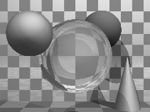 Ray tracing has the tremendous advantage that it can produce realistic
looking images. The technique allows a wide variety of lighting
effects to be implemented. It also permits a range of primitive shapes
which is limited only by the ability of the programmer to write an
algorithm to intersect a ray with the shape.
Ray tracing works by firing one or more rays from the eye point
through each pixel. The colour assigned to a ray is the colour of the
first object that it hits, determined by the object's surface
properties at the ray-object intersection point and the illumination
at that point. The colour of a pixel is some average of the colours of
all the rays fired through it. The power of ray tracing lies in the
fact that secondary rays are fired from the ray-object intersection
point to determine its exact illumination (and hence colour). This
spawning of secondary rays allows reflection, refraction, and
shadowing to be handled with ease.
Ray tracing's big disadvantage is that it is slow. It takes minutes,
or hours, to render a reasonably detailed scene. Until recently, ray
tracing had never been implemented in hardware. A Cambridge company,
Advanced Rendering Technologies,
is trying to do just that, but they will probably still not get ray
tracing speeds up to those achievable with polygon scan conversion.
Ray tracing is used where realism is vital. Example application areas
are high quality architectural visualisations, and movie or television
special effects.
Example
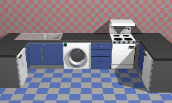 This kitchen was rendered using the ray tracing program rayshade.
 These close-ups of the kitchen scene show some of the power of ray
tracing. The kitchen sink reflects the wall tiles. The benchtop in
front of the kitchen sink has a specular highlight on its curved front
edge.
 The washing machine door is a perfectly curved object (impossible to
achieve with polygons). The inner curve is part of a cone, the outer
curve is a a cylinder. You can see the floor tiles reflected in the
door. Both the washing machine door and the sink basin were made
using CSG techniques (see Part 4C).
 The grill on the stove casts interesting shadows (there are two lights
in the scene). This sort of thing is much easier to do with ray
tracing than with polygon scan conversion.
Polygon scan conversion
 This term encompasses a range of algorithms where polygons are
rendered, normally one at a time, into a frame buffer. The term
scan comes from the fact that an image on a CRT is made up of
scan lines. Examples of polygon scan conversion algorithms are
the painter's algorithm, the z-buffer, and the A-buffer
(FvDFH chapter 15 or F&vD chapter 15). In
this course we will generally assume that polygon scan conversion
(PSC) refers to the z-buffer algorithm or one of its
derivatives.
The advantage of polygon scan conversion is that it is fast. Polygon
scan conversion algorithms are used in computer games, flight
simulators, and other applications where interactivity is
important. To give a human the illusion that they are interacting with
a 3D model in real time, you need to present the human with animation
running at 10 frames per second or faster. Polygon scan conversion can
do this. The fastest hardware
implementations of PSC algorithms can now process millions of polygons per
second.
One problem with polygon scan conversion is that it can only support
simplistic lighting models, so images do not necessarily look
realistic. For example: transparency can be supported, but refraction
requires the use of an advanced and time-consuming technique called
"refraction mapping"; reflections can be supported -- at the expense
of duplicating all of the polygons on the "other side" of the
reflecting surface; shadows can be produced, by a more complicated
method than ray tracing. The other limitation is that it only has a
single primitive: the polygon, which means that everything is made up
of flat surfaces. This is especially unrealistic when modelling
natural objects such as humans or animals. An image generated using a
polygon scan conversion algorithm, even one which makes heavy use of
texture mapping, will tend to look computer generated.
Examples


Texture mapping is a simple way of making a PSC (or a
RT) scene look better without introducing lots of polygons. The
image above left shows a scene without any texture maps. The equivalent
scene with texture maps is shown above right. Obviously this scene was
designed to be viewed with the texture maps turned on. This example
shows that texture mapping can make very simple geometry look
interesting to a human observer.
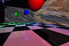
 The image at left was generated using PSC. Texture mapping has
been used to make the back and side walls more interesting. All the
objects are reflected in the floor. This reflection is achieved by
duplicating all of the geometry, upside-down, under the floor, and
making the floor partially transparent. The close-up at right shows
the reflection of the red ball, along with a circular "shadow" of the
ball. This shadow is, in fact, a polygonal approximation to a circle
drawn on the floor polygon and bears no relationship to the lights
whatsoever.
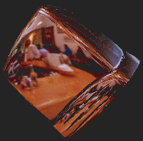
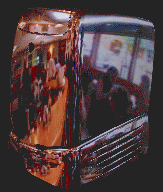 Environment mapping is another clever idea which makes PSC
images look more realistic. In environment mapping we have a texture
map of the environment which can be thought of as wrapping completely
around the entire scene (you could think of it as six textures on the
six inside faces of a big box). The environment map itself is not
drawn, but if any polygon is reflective then the normal to the polygon
is found at each pixel (this normal is needed for Gouraud shading
anyway) and from this the appropriate point (and therefore colour) on
the environment map can be located. This example shows a silvered SGI
O2 computer reflecting an environment map of the interior of a cafe.

PSC is, of course, widely used in interactive games. Here we see
an incautious opponent about to drive into our player's sights. The
graphics are not particularly sophisticated: there are very few
polygons in the scene, but the scene is made more interesting,
visually, by using texture mapping. When playing the game people tend
to worry more about winning (or, in some cases, not losing too badly)
than about the quality of the graphics. Graphical quality is arguably
more useful in selling the game to the player than in actual game
play.
Line drawing
An alternative to the above methods is to draw the 3D model as a wire
frame outline. This is obviously unrealistic, but is useful in
particular applications. The wire frame outline can be either see
through or hidden lines can be removed (FvDFH section 15.3
or F&vD section 14.2.6). In general, the lines that
are drawn will be the edges of the polygons which would be drawn by
a PSC algorithm.
Line drawing is generally faster than PSC unless the PSC
is being done by specialist hardware. Line drawing of 3D models is
used in Computer Aided Design (CAD) and in 3D model design. The
software which people use to design 3D models for ray tracing tends to
use both LD and PSC in its user interface. It is
interesting to note that, when R&A was first written
(1976), the authors had only line drawing algorithms with which to
illustrate their 3D models. The only figure in the entire book which
does not use exclusively line drawing is Fig. 6-52, which has screen
shots of a prototype PSC system.
Out in the real world...
3D graphics finds applications in three main areas:
- visualisation -- scientific, medical, and architectural
- simulation -- for example, flight simulators
- entertainment -- movie and TV special effects and games
Visualisation generally does not require realistic looking images. In
science we are usually visualising complex three dimensional
structures, such as protein molecules, which have no "realistic"
visual analogue. In medicine we generally prefer an image that helps
in diagnosis over one which looks beautiful. PSC is therefore
normally used in visualisation (although some data require voxel
rendering -- see Part 4D).
Simulation uses PSC because it can generate images at
interactive speeds. At the high (and very expensive) end a great deal
of computer power is used. In the most expensive flight simulators
(those with full hydraulic suspension and other fancy stuff) the
graphics kit can cost £1,000,000 out of a total cost of about ten
times that figure.
3D games (for example Quake, Unreal, Descent) use PSC because it
gives interactive speeds. A lot of other "3D" games (for example SimCity, Civilisation, Diablo) use pre-drawn sprites (small
images) which they simply copy to the appropriate position on the
screen. This essentially reduces the problem to an image compositing
operation, requiring much less processor time. The sprites can be hand
drawn by an artist or created in a 3D modelling package and rendered
to sprites in the company's design office. Donkey Kong Country, for
example, uses sprites which were ray traced from 3D models.
You may have noticed that the previous sentence is the first mention
of ray tracing in this section. It transpires that the principal use of
ray tracing, in the commercial world, is in producing special effects
for movies and television.
The first movie to use 3D computer graphics was Star Wars [1977]. You may
remember that there were some line drawn computer graphics toward the
end of the movie. All of the spaceship shots, and all of the other
fancy effects, were done using models, mattes (hand-painted
backdrops), and hand-painting on the actual film. Computer graphics
technology has progressed incredibly since then. The recent re-release
of the Star Wars trilogy included a number of computer graphic
enhancements, all of which were composited into the original
movie.
A recent example of computer graphics in a movie is the (rather
bloodythirsty) Starship
Troopers [1997]. Most of the giant insects in the movie are
completely computer generated. The spaceships are a combination of
computer graphic models and real models. The largest of these real
models was 18' (6m) long: so it is obviously still worthwhile
spending a lot of time and enrgy on the real thing.
Special effects are not necessarily computer generated. Compare King Kong
[1933] with Godzilla
[1998]. The plots have not changed that much, but the special effects
have improved enormously: changing from hand animation (and a man in a
monkey suit) to swish computer generated imagery. Not
every special effect you see in a modern movie is computer
generated. In Starship Troopers, for example, the explosions
are real. They were set off by a pyrotechnics expert against a dark
background (probably the night sky), filmed, and later composited into
the movie. In Titanic [1997] the
scenes with actors in the water were shot in the warm Gulf of
Mexico. In order that they look as if they were shot in the freezing
North Atlantic, cold breaths had to be composited in later. These were
filmed in a cold room over the course of one day by a special effects
studio.Film makers obviously need to balance quality, ease of
production, and cost. They will use whatever technology gives them the
best trade off. This is increasingly computer graphics, but computer
graphics is still not useful for everything by quite a long way.
A recent development is the completely computer generated movie. Toy
Story [1995] was the world's first feature length computer
generated movie. Two more were released last year (A Bug's Life [1998] and Antz [1998]). Toy Story 2 [1999] will be
released in the UK on 4 February 2000.
PSC or RT for SFX?
While RT gives better results than PSC, we can often get
acceptable results with PSC through the use of techniques such
as environment mapping and the use of lots and lots and lots of tiny
polygons. The special effects industry still dithers over whether to
jump in and use RT. Many special effects are done using
PSC, with maybe a bit of RT for special things (giving a
hybrid RT/PSC algorithm). Toy Story, for example,
used Pixar's proprietary PSC algorithm. It still took between 1
and 3 hours to render each frame (although you must remember that
these frames have a resolution of about 2,000 by 1,000 pixels). More
expensive algorithms can be used in less time if you are rendering for
television (I estimate that about one sixth of the pixels are
needed compared to a movie) or if you are only rendering a small part
of a big image for compositing into live action.
Finally, at SIGGRAPH 98 I had the chance to hear about the software
that some real special effects companies are using:
- BlueSky|ViFX
- Everything is ray traced using CGI-Studio.
- Digital Domain
- Use ray tracing in commercial software, except when the commercial
software cannot do what they want. Used MentalRay on Fifth Element
[1997]; used Alias
models (NURBS) passed to Lightwave (polygons) for one
advertisement; used MentalRay
plus Renderman
for another advertisement.
- Rhythm + Hues
- Use a proprietry renderer, which is about 10 years old. It has
been rewritten many times. They make only limited use of ray tracing.
- Station X
- Use Lightwave plus an
internally developed renderer which is a hybrid between ray tracing
and z-buffer.
Exercises
- Compare and contrast the capabilities and uses of ray tracing and
polygon scan conversion.
- In what circumstances is line drawing more useful than either ray
tracing or polygon scan conversion.
- (a) When is realism critical? Give 5 examples of applications
where different levels of visual realism are necessary. Choose ray
tracing or polygon scan conversion for each application and
explain why you made your choice. (b) How would you determine what
level of visual realism is `necessary' for a given application?
- "The quality of the special effects cannot compensate for a bad
script." Discuss with reference to (recent) movies that you have seen.
|
1B) Polygon mesh management
Relevant mainly to PSC and LD.
Drawing polygons
In order to draw a polygon, you obviously need to know its
vertices. To get the shading correct you also need to know its
orientation: which side is the front of the polygon and which is the
back. Many systems assume one-sided polygons: the front side is shaded
and the back side either is coloured matt grey or black or is not even
considered. This is sensible if the polygon is part of a closed
polyhedron. In many applications, all objects consist of closed
polyhedra; but you cannot guarantee that this will always be the
case, which means that you will get unexpected results when the back
sides of polygons are actually visible on screen.
The orientation of a polygon is specified by its normal vector. This
does not need to be specified independently of the polygon's vertices
because it can be calculated from the vertices. As an example: assume
a polygon has three vertices, A, B and C. The
normal vector can be calculated as: n = (C-B) x
(A-B).
Any three adjacent vertices in a polygon can be
used to calculate the normal vector but the order in which the
vertices are specified is important: it changes whether the vector
points up or down relative to the polygon. In a right-handed
co-ordinate system the three vertices must be specified anti-clockwise
round the polygon as you look down the desired normal vector (i.e. as
you look at the front side of the polygon). Note that, if there are more than
three vertices in the polygon, they must all lie in the same plane,
otherwise the shape will not be a polygon!
Thus, for drawing purposes, we need to know only the vertices and
surface properties of the polygon. The vertices naturally give us both
edge and orientation information. The surface properties are such
things as the specular and diffuse colours, and details of any texture
mapping which may be applied to the polygon.
Interaction with polygon mesh data
The above is fine for drawing but, if you wish to manipulate the
polygon mesh (for example, in a 3D modelling package), then is is
useful to know quite a lot more about the connectivity of the
mesh. For example: if you want to move a vertex, which is shared by
four polygons, you do not want to have to search through all the
polygons in your data structure trying to find the ones which contain
a vertex which matches your vertex data.
The winged-edge data structure is particularly useful for
handling polygon mesh data. It contains explicit links for all of the
relationships between vertices, edges and polygons, thus making it
easy to find, for example, which polygons are attached to a given
vertex, or which polygons are adjacent to a given polygon (by
traversing the edge list for the given polygon, and finding which
polygon lies on the other side of each edge).
The vertex object contains the vertex's co-ordinates, a pointer to a
list of all edges of which this vertex is an end-point, and a pointer
to a list of all polygons of which the vertex is a vertex.
The polygon object contains (a pointer to) the polygon's surface
property information, a pointer to a list of all edges which bound
this polygon, and a pointer to an ordered list of all vertices of the
polygon.
The edge object contains pointers to its start and end vertices, and
pointers to the polygons which lie to the left and right of it.
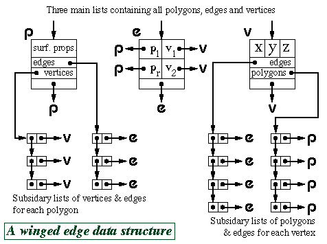
The above diagram shows just one possible implementation of a polygon
mesh data structure. FvDFH section 12.5.2 describes another
winged-edge data structure which contains slightly less information,
and therefore requires more accesses to find certain pieces of
information than the one shown above. The implementation that would be
chosen depends on the needs of the particular application which is
using the data structure. Another alternative would be to attach
shading information to vertices rather than to polygons. This could
then be used to Gouraud shade or Phong shade the polygons.
F&vD section 13.2 also contains a
bit of information on polygon meshes.
Hardware PSC quirks
A piece of PSC hardware, such as the
Silicon Graphics Reality Engine, will
generally consist of a geometry engine and a rendering engine.
The geometry engine will handle the transformations of all vertices
and normals (and possibly handle some of the shading
calculations). The rendering engine will implement the PSC
algorithm on the transformed data.
Triangles only
When making a piece of hardware to render a polygon, it is much easier
to make the hardware handle a fixed number of vertices per polygon,
than a variable number. Many hardware implementations thus simply
implement triangle drawing. This is not a serious drawback. Polygons
with more vertices are simply split into triangles.
The triangle strip set and triangle fan set
In addition to simple triangle drawing, Silicon Graphics machines
implement both the triangle strip set and triangle fan set to speed up
processing through the geometry engine. Each triangle in the set has
two vertices in common with the previous triangle. Each vertex is
transformed only once by the geometry engine, giving a factor of three
speed up in geometry processing.
For example, assume we have triangles ABC, BCD,
CDE and DEF. In standard triangle rendering, the
vertices would be sent to the geometry engine in the order ABC BCD
CDE DEF; each triangle's vertices being sent separately. With a
triangle strip set the vertices are sent as ABCDEF; the
adjacent triangles' vertices overlapping.
A triangle fan set is similar. In the four triangle case we would have
triangles ABC, ACD, ADE and AEF. The
vertices would again be sent just as ABCDEF. It is obviously
important that the rastering engine be told whether it is drawing
standard triangles or a triangle strip set or a triangle fan set.
Exercises
- Calculate both surface normal vectors (left-handed and
right-handed) for a triangle with points (1, 1, 0), (2, 0, 1), (-1,
-2, -1).
- Confirm that the following statements are correct for a
reasonable polygon mesh:
- A vertex belongs to at least
two edges.
- A vertex is a vertex of at least one polygon.
- An
edge has exactly two end points.
- An edge is an edge of either one
or two polygons.
- A polygon has at least three vertices.
- A
polygon has at least three edges.
- Work out the algorithm that is required to modify a winged-edge
data structure when an edge is split. You may ignore surface property
information for the polygons and you may assume that the edge that is
split is split exactly in half. The algorithm could by called by the
function call:
split_edge( vertex_list v, edge_list e,
polygon_list p, edge edge_to_split)
where the winged-edge
data structure is made up of the three linked lists of objects
(vertices, edges, and polygons).
|
2A) Ray tracing primitives
Relevant mainly to RT.
A primitive is a shape for which a ray-shape intersection
routine has been written. More complex objects can be built out of the
primitives. Most ray tracers will have a variety of primitives. They
are limited only by the ability of the programmer to write a function
to analytically intersect a ray with the surface of the shape.
Common primitives
Plane
The infinite plane is a simple object with which to intersect a ray
(see Part IB notes for details). On its own it
can represent boundary objects such as the ground or the sky or
perhaps an infinite wall. Intersection with the infinite plane is a
useful building block in a ray tracing system.
 Polygon
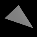
Having the polygon as a ray tracing primitive allows a ray tracer to
render anything that a PSC algorithm could. To find the
intersection of a ray with a polygon, first find the intersection of
the ray with the infinite plane in which the polygon lies. Then
ascertain whether the intersection lies inside or outside the polygon:
this is a reasonably straightforward two dimensional graphics operation.
 Box
Box
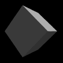
A box is essentially six polygons and could be ray traced as
such. However, intersection with an axis-aligned box can be
optimised. Any box can be axis-aligned by appropriate
transformations. We can thus write a routine to intersect an arbitrary
ray with an axis-aligned box and then transform the ray under
consideration in exactly the same way as we transform the box which we are
trying to intersect with it. This sort of idea generalises neatly to
the concept of specifying any object in a convenient object coordinate
system and then applying transforms to the whole object to place
it at the appropriate point in the world coordinate system.
 Sphere
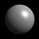
The sphere is the simplest finite object with which to intersect a
ray. Practically any ray tracing program will include the sphere as a
primitive. Scaling a sphere by different amounts along the different
axes will produce an ellipsoid: a squashed or stretched sphere. There
is thus no need to include the ellipsoid as a primitive provided that
your ray tracer contains the usual complement of transformations. (It
would be a poor ray tracer if it did not!)
 Cylinder
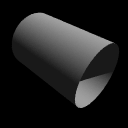
Intersecting a ray with an infinitely long cylinder is practically as
easy as intersecting one with a sphere. The tricky bit, if it can be
called that, is to intersect a ray with a more useful finite length
cylinder. This is achieved by intersecting the ray with the
appropriate infinitely long cylinder and then ascertaining where along
the cylinder the intersection lies. If it lies in the finite length in
which you are interested then keep the intersection. If it does not
then ignore the intersection. Note that the ray tracer used to render
the accompanying image has cylinders without end caps. This is the
correct result if you follow the procedure outlined in this
paragraph. Adding end caps to your cylinders requires extra
calculations.
 Cone
Cone
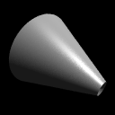
Cones are very like cylinders. Like the infinite cylinder, there is a
simple mathematical definition of an infinite cone which makes it easy
to write a ray-cone intersection algorithm. Note that a cone does not
need to have a point -- it can be truncated short of its `top', as
illustrated in the accompanying image. The particular ray
tracer used does not add end caps to cones.
 Disc
Disc
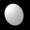
The disc is not a common ray tracing primitive, but is necessary in
ray tracers which implement cones and cylinders without end caps. It
is handled in much the same way as the polygon. The
routine to check if the intersection with the plane lies inside or
outside of the disc is simpler than the equivalent routine for the
polygon. In the accompanying ray traced image, the disc has been
positioned so that it just catches the light -- this illustrates how
specular reflection varies across a completely flat surface. The
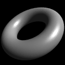
sphere, cone and torus images illustrate how specular reflection varies
across three curved surfaces.
 Torus
Torus
Toroids are reasonably rare in real life (doughnuts and tyre inner
tubes notwithstanding). They are somehow alluring to the kinds of
people who implement ray tracers and, having a reasonably
straightforward mathematical definition, are reasonably simple to
implement. They thus appear as primitives in many ray tracers. They
become more useful when combined with Constructive Solid Geometry (see
Part 4C).
Ray-primitive intersections
SMAG section 1 contains the
mathematics of ray-primitive intersections and details of how you
would go about converting a primitive object into polygons for
PSC.
Exercises
- Work out mathematical equations to define a plane, a sphere, an
infinitely long cylinder, an infinitely long cone, and a torus. You
will find it helpful to centre each primitive at the origin and to
align it in a sensible way with respect to the coordinate axes. You
may like to use cylindrical polar coordinates where these prove
useful. As a starting point remember that a circle can be represented
by the equation:

- Work out a way to intersect a ray with each of the five
primitives. You may assume that you are provided with functions to
find the roots of linear, quadratic, cubic and quartic equations.
- Work out if there exists a faster intersection algorithm for an
axis aligned 2x2x2 unit box than just six separate polygon
intersection calculations (N.B. I don't know whether there is or not).
- [1999/7/11] (a) Give a parametric definition of a torus centred at
the origin and aligned with the coordinate axes. (b) Outline how you
would find the first intersection point, if any, of a ray with the
torus from the previous part.
- Show how to convert a cylinder into a polygon mesh. What changes
do you have to make if the mesh may contain only
triangles?
- Show how to convert a torus into a polygon mesh.
- Show how to convert a sphere into a triangle mesh. How can you get
the most even distributiuon of triangle vertices across the
sphere?
|
2B) Conics, quadrics, and superquadrics
The ray tracing primitives, described in Part
2A, have relatively simple mathematical definitions. This is what
makes them attractive: the simple mathematical definition allows for
simple ray-object intersection code. Following from this, it would
seem logical to investigate other shapes with simple mathematical
definitions. Spheres, cones and cylinders are part of a more general
family of parametric surfaces called quadrics (N.B. tori are
not quadrics). Quadrics are the 3D analogue of 2D conics. We
describe these general families below, but it turns out that they are
of little practical use. It would seem that the general quadrics are a
"dead end" in graphics research.
Conics
A conic is a two dimensional curve desribed by the general
equation:

This general form can be rotated, scaled, and translated so that it is
aligned along the axes of the coordinate system. It will then have the
simpler equation:

The useful conics are the ellipse (of which the circle is a special
case), the hyperbola, and the parabola. For more details see
R&A section 4-10, especially Table 4-8 on page 242.
Table 4-8 is included in the handout.
Quadrics
The quadrics are the three dimensional analogue of the conics. The
general equation is:

This general form can be rotated, scaled, and translated so that it is
aligned along the axes of the coordinate system. It will then have the
simpler equation:

The useful conics are the ellipsoid (of which the sphere is a special
case), the infinite cylinder, and the infinite cone. Various
hyperboloids, and paraboloids are also defined by these equations, but
these have little real use unless one is designing satellite dishes
(paraboloid), headlamp reflectors (also paraboloid), or power
station cooling towers (hyperboloid). For more details see
R&A section 6-4, especially Figure 6-18 on page 403.
Figure 6-18 is included in the handout.
Superquadrics
These are an extension of quadrics, where the power on the coordinate
does not have to be 2. The general form of a superquadric centred at
the origin and aligned along the coordinate axes is:

Super-ellipsoids tend to be the only members of this family that are
actually used, and even they are only used in very limited areas. The
effect of n on a super-ellipsoid is roughly as follows:
n=2 is a standard ellipsoid; n<2 is a more pointy
version, the "points" being along the main axes; n>2 becomes
closer to a box as n increases; n=1 is allegedly an
octahedral shape; and n<1 is truly pointy along the main
axes.
The interested student may like to have a quick look at Alan
Barr's two papers on superquadrics. The papers can be found in the Computer
Laboratory library in IEEE Transactions on Computer Graphics and
Applications volume 1, number 1 (January 1981), pages 11-23, and
volume 1, number 3 (July 1981), pages 41-47.
Brian Wyvill describes a use of super-ellipsoids on pages 264 and 265
of "A Computer Animation Tutorial" in Computer Graphics Techniques:
Theory and Practice, Rogers and Earnshaw (editors),
Springer-Verlag, 1990, ISBN 0-387-97237-4.
This extract is included in the handout.

 The image at left was generated using PSC. Texture mapping has
been used to make the back and side walls more interesting. All the
objects are reflected in the floor. This reflection is achieved by
duplicating all of the geometry, upside-down, under the floor, and
making the floor partially transparent. The close-up at right shows
the reflection of the red ball, along with a circular "shadow" of the
ball. This shadow is, in fact, a polygonal approximation to a circle
drawn on the floor polygon and bears no relationship to the lights
whatsoever.
 Ray tracing has the tremendous advantage that it can produce realistic
looking images. The technique allows a wide variety of lighting
effects to be implemented. It also permits a range of primitive shapes
which is limited only by the ability of the programmer to write an
algorithm to intersect a ray with the shape.
 This kitchen was rendered using the ray tracing program rayshade.
 These close-ups of the kitchen scene show some of the power of ray
tracing. The kitchen sink reflects the wall tiles. The benchtop in
front of the kitchen sink has a specular highlight on its curved front
edge.
 The washing machine door is a perfectly curved object (impossible to
achieve with polygons). The inner curve is part of a cone, the outer
curve is a a cylinder. You can see the floor tiles reflected in the
door. Both the washing machine door and the sink basin were made
using CSG techniques (see Part 4C).
 The grill on the stove casts interesting shadows (there are two lights
in the scene). This sort of thing is much easier to do with ray
tracing than with polygon scan conversion.
 This term encompasses a range of algorithms where polygons are
rendered, normally one at a time, into a frame buffer. The term
scan comes from the fact that an image on a CRT is made up of
scan lines. Examples of polygon scan conversion algorithms are
the painter's algorithm, the z-buffer, and the A-buffer
(FvDFH chapter 15 or F&vD chapter 15). In
this course we will generally assume that polygon scan conversion
(PSC) refers to the z-buffer algorithm or one of its
derivatives.


 Environment mapping is another clever idea which makes PSC
images look more realistic. In environment mapping we have a texture
map of the environment which can be thought of as wrapping completely
around the entire scene (you could think of it as six textures on the
six inside faces of a big box). The environment map itself is not
drawn, but if any polygon is reflective then the normal to the polygon
is found at each pixel (this normal is needed for Gouraud shading
anyway) and from this the appropriate point (and therefore colour) on
the environment map can be located. This example shows a silvered SGI
O2 computer reflecting an environment map of the interior of a cafe.


 Polygon
 Box
Box Sphere
 Cylinder
 Cone
Cone Disc
Disc Torus
Torus