3A) Bezier curves
Bezier curves were covered in the Part IB
Computer Graphics and Image Processing course. SMAG section 2 gives some of the
mathematical details, as does R&A Section 5-8.
Parts of this Section of R&A are included in the handout.
Exercises
- Explain what C0-, C1-, C2-, Cn-continuity mean.
- Derive the constraints on control point positions which ensure
that two quartic Bezier curves join with (a) C0-continuity, (b)
C1-continuity, and (c) C2-continuity.
|
3B) B-splines.
B-splines are covered in some detail in SMAG section 3 and in R&A Section 5-9.
Parts of this Section of R&A are included in the
handout. Beware that none of the worked examples are in the
handout. These may come in useful, and you will need to get hold of a
real copy of R&A if you wish to work your way through them.
Why B-splines?
B-splines have many nice properties when compared to other families of
curves which could be used. They:
- minimise the order of the polynomial pieces (order k)
- maximise the continuity between pieces (continuity C(k-2))
- minimise the number of control points controlling a piece (k points)
- have positive basis functions
- have basis functions which partition unity, implying that each piece lies
inside its control points' convex hull
- are invarient with respect to affine transforms
Exercises
- How many control points are required for a quartic Bezier and how
many for a quartic B-spline?
- Why are cubics the default for B-spline use?
- Explain the difference between Uniform, Open Uniform, and
Non-Uniform knot vectors. What are the advantages of each type?
|
3C) NURBS
NURBS are covered in SMAG section
4 and in some detail in R&A Section 5-13.
Parts of this Section of R&A
are included in the handout.
Non-uniform rational B-splines are the curves that are currently used
in any graphics application that requires curves and surfaces with
more functionality than Bezier curves can offer. In addition to the
features listed in Part 3B, NURBS are
invarient with respect to perspective transforms.
NURBS curves incorporate -- as special cases -- uniform B-splines,
non-rational B-splines, Bezier curves, lines, and conics. NURBS
surfaces incorporate planes, quadrics, and tori.
Exercises
- Review from IB: What are homogeneous
coordinates and what are they used for in computer graphics?
- Explain how to use homegeneous coordinates to get rational
B-splines given that you know how to produce non-rational B-splines.
- Convince your supervisor that you understand why NURBS includes
Uniform B-splines, Non-Rational B-splines, Beziers, lines, conics,
quadrics, and tori.
- When would you use Bezier curves and when would you use B-splines?
(i.e. why have B-splines, in general, replaced Bezier curves in CAD?)
- [1998/7/12] Consider the design of a user interface for a NURBS
drawing system. Users should have access to the full expressive power
of the NURBS representation. What things should users be able to
modify to give them such access and what effect does each have on the
resulting shape?
- For each of the items (in the previous question) that the user can
edit: (i) Give sensible default values; (ii) Explain how they would be
constrained if a `demo' version of the software was to be limited to
cubic Uniform Non-rational B-Splines.
- [1999/7/11] (c) Show how to construct a circle using non-uniform
rational B-splines (NURBS). (d) Show how the circle definition from
the previous part can be used to define a NURBS torus. [You need
explain only the general principle and the location of the torus'
control points.]
|
4A) Generative models
Sweeps
These are three dimensional objects generated by sweeping a
two dimensional shape along a path in 3D. Two special cases of the
sweep are surfaces of revolution, where the path is
a circle; and extrusions, where the path is a straight line.
Surfaces of revolution are covered in R&A section
6-2. Sweeps are covered in R&A section
6-3 and FvDFH section 12.4.
Parts of Sections 6-2 and 6-3 of R&A are included in the handout.
Extrusion

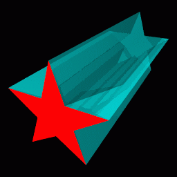
On the left (above) is an example extrusion. On the right is its generating polygon (the red star), with the generated 3D object shown in semi-transparent cyan.
Surface of revolution
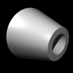
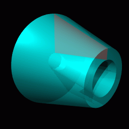
 On the left
(above) is an example surface of revolution. On the right (above) is
its generating quadrilateral (the red polygon), with the generated 3D
object shown in semi-transparent cyan. Below that is another view of
the same surface of revolution.
Revolution or extrusion?
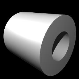
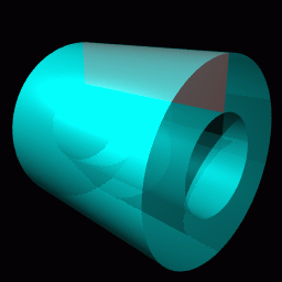
 Some objects can be generated in more than one way. The hollow
cylinder shown above (left) could be generated as either a surface of
revolution (above right) or as an extrusion (immediately right).
General sweeps
If we push the idea of a sweep to its limit we can think of many
things which could be modified to produce a three dimensional swept
shape:
-
Cross section
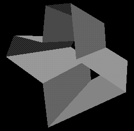
 Some two dimensional shape that is to be swept along the sweep
path. It does not have to be circular. At right are two swept objects,
one with a circular cross-section, one with a polygonal cross-section.
-
Sweep path
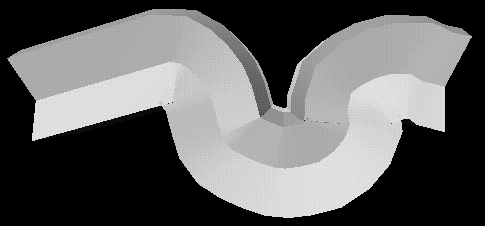
 The path along which the two dimensional cross section is swept to
produce the three dimensional shape. It may be any curve. At right we
see two views of the same swept object: a polygonal
cross-section is swept along a convoluted path.
-
Twist
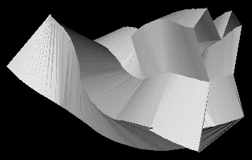
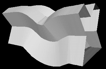 How the cross section twists (rotates) as it moves along the sweep
path. The default would be to have no twist at all. At right is a
swept object with and without some twist.
-
Scale


How the cross section scales (changes size) as it moves along the
sweep path. The default would be to have it stay the same size along
the whole path. Above are a cylinder, and the same cylinder with
different scales along its length.
-
Normal vector direction
The normal vector of the 2D cross section will usually
point along the sweep path at each point. Changing this will change the
nature of the swept object. See R&A Figure 6-17
(in the handout)
for an example.
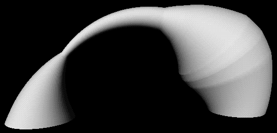 At right is a swept object with a circular cross-section,
semi-circular path, and varying scale.
You may be able to think of parameters, other than those in the list
above, which could be modify.
Exercises
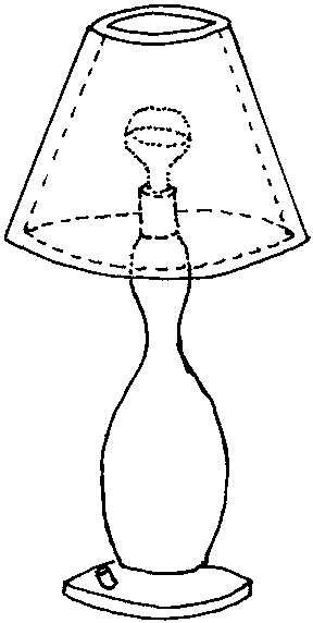
- [1998/7/12] Show how the following object can be represented as a
swept object.


- Use the following different methods of specifying a geometrical
model for this picture (assuming it's a three dimensional model and not
a line drawing). Come as close as you can to the original for any of the
methods, and describe the difficulties in using a particular method for
this model.
- Extrusions
- Surfaces of revolution
- General sweeps
- For each of the following categories list five real-world objects
which could be represented by the primitives in the category.
- The ray-tracing primitives in Part 2A
- Extrusions
- Surfaces of revolution
- General sweeps
- A flume (water tunnel) at a swimming complex is modeled as a
circle swept along a particular path. The designers also want to model
the volume swept out by a person traveling down the flume. (We can
approximate the cross-section of a person with something roughly
elliptical and we'll assume the `virtual' person doesn't move legs or
arms while hurtling along.) Explain which parameters in the list
would be need to be modified to specify the shape of the flume and
which would need to be modified to model the volume swept out by a
person traveling down the flume (alternatively, specify which
parameters would be held constant, in each case, for the entire length
of the sweep).
|
4B) Converting swept objects to polygons
Swept objects are hard to ray trace. Imagine trying to write a
ray/object intersection algorithm for a general swept object.
This means that we generally need to polygonise swept objects in
order to render them. For PSC we obviously must convert them to
polygons.
A swept surface may be easily converted to polygons by converting the
outline of the 2D cross section to a polygon, and converting the sweep
path to connected set of line segments. Moving the polygon to each
vertex of the set of line segments, and connecting vertices
accordingly, will produced a polygon mesh which approximates the swept
surface.
Exercises
- [1998/7/12] Show how to convert the swept object from Part 4A Exercise 1 into polygons. What extra
work would you need to do if you had to convert it into triangles?
|
4C) Constructive Solid Geometry
Constructive solid geometry (CSG) essentially consists of Boolean set
operations on closed primitives in 3D space. The three CSG operations
are union, intersection and difference.
CSG is covered in FvDFH sections 12.7 and 15.10.3.
The following example illustrates the three CSG operations in use on
simple three dimensional primitives.

 The two primitives: a sphere and a box.
 The union of the two primitives.
 The intersection of the two primitives.
 The difference of the two primitives: box minus sphere.
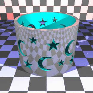
The following example, based on FvDFH Plate III.2, shows an
object for which CSG is (probably) the only sensible modelling
technique. The object rendered in the right-hand image is constructed
from the primitives shown in the left-hand image. It is mostly made
out of cylinders, but you will recognise the extruded star from Part 4A.
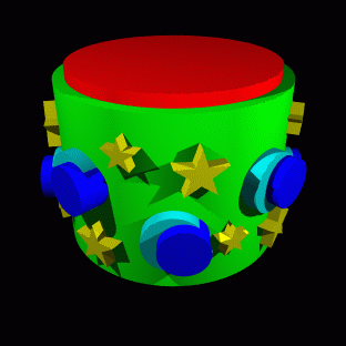
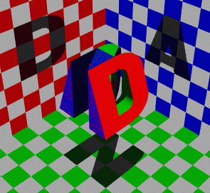 At right, I tried the "Godel, Escher, Bach" treatment on my initials.
Unfortunately the letters N, A, and D are not as amenable to this as
the letters G, E, and B: notice that the shadow of the N has a slight
curve at its top right, owing to the N's intersection with the curve
on the D and the slope on the A. Various other arrangements of the
three letters were tried, all of which gave more noticable artefacts
than this. Each of the letters is a CSG object (the D, for example,
is constructed from cylinders and boxes). The final effect is produced
simply by intersecting the three letters.
Exercises
- Work out how to represent a Lego technic brick as a CSG
object. You may assume that you have box and cylinder primitives.


- [1998/7/12] Work out how to represent the following object using CSG. You may assume the following primitives: sphere, cylinder, cone, torus, box.


- [1999/9/4] (c) List the three ways of combining objects using
constructive solid geometry (CSG). Describe how an object built using
CSG can be represented using a binary tree. Given the intersection
points of a ray with each primitive in the tree, explain how these
points are passed up the tree by each type of combination node to
produce a list of intersection points for the whole CSG object.
|
4D) Implicit surfaces, voxels and the marching cubes algorithm
Implicit surfaces
These are covered in Brian Wyvill's article "A Computer
Animation Tutorial" in Computer Graphics Techniques: Theory and
Practice, Rogers and Earnshaw (editors), Springer-Verlag, 1990,
ISBN 0-387-97237-4.
The relevant pages of this book (258-271) are included in the
handout. Note that the section on Animating SOFT Objects (pages
268-271) is for interest only, and is not examinable.
Voxels and the marching cubes algorithm
Voxels are the three dimensional analogue of pixels. Rather than
storing a colour in a voxel, you will generally store a density
value. Voxels and the marching cubes algorithm are both covered in
Lorenson and Cline's 1987 SIGGRAPH paper "Marching cubes: a high
resolution 3D surface construction algorithm", Proc SIGGRAPH
87, pages 163-169.
This paper is included in the handout. One of the reasons for
including the paper is to give you a taster of what a good graphics
research paper looks like. Two of the exercises relate to evaluating
this paper in terms of (i) its research content and (ii) its written
style..
Exercises
- Give a definition of an implicit surface and give three examples of
where such things might be useful.
- The marching cubes algorithm, as it applies to implicit surfaces,
is described in the Wyvill article; while Lorenson and Cline
concentrate on the algorithm as applied to voxel data. It is useful
that the same algorithm works for both types of data. Explain how
voxel data can be thought of a defining an implicit surface (or
surfaces). Explain, conversely, how the Wyvill algorithm can be
thought of as converting implicit surface data into voxel data before
producing the final surface.
- Following Section 4 of Lorenson and Cline's paper, sketch an
implementation of the two-dimensional `marching squares' algorithm --
where you generate line segments in 2D rather than triangles in 3D. An
appliation of this algorithm would be the drawing of isobars on a
weather map, given pressure values at a regular (2D) grid of points.
- Medical data is captured in slices. Each slice is a 2D image of
density data. The distance between slices may be different to the
distance between the pixels within a slice (for example, see Lorenson
and Cline, Section 7.1, p. 167). What effect does this difference have
on the voxel data? What effect does it have on the marching cubes
algorithm?
- Consider Lorenson and Cline, Section 6. This research was done
about twelve years ago. Given your knowledge of processor performance,
what differences in performance would you expect to see between then
and now?
- Lorenson and Cline is an example of a graphics research
paper. Critically evaluate Lorenson and Cline. How good is this piece
of research?
- Research papers at the SIGGRAPH conference are limited in their
length. Evaluate Lorenson and Cline in terms of the following
questions. What has been left out that would have been useful? What
has been included that could have been left out? Where could the
explanation have been better? Are any of the figures extraneous? Where
would an extra figure have been helpful? List any grammatical or
spelling errors (there is at least one of each).
|
5) Radiosity
The hand-written notes in the handout contain all of the information
for this part of the course.
Exercises
- Explain what lighting effects radiosity is trying to model that
are not modelled by RT or PSC.
- Describe the basic radiosity algorithm.
- [1999/9/4] (d) Explain what a form factor is, in radiosity.
Outline an implementable method of calculating form factors.
|
Human-Computer Interaction
The material for this section of the course will be
handed out in lectures.
|
Exercises
These exercises relate to Parts 6 and 7 of the syllabus.
- Fitts' Law: What changes when you have older users? When you
measure the speed with which someone can move their elbow? When you
measure underwater?
- Rate the importance of: Speed of Use, Computational Resources,
Ease of Learning, Ease of Rememberance, Error Potential for the
following applications:
- Airplane autopilot controls
- Word processor
- Push bar on exit door
- VCR
- Mechanical pencil
- Air traffic control display
- Quake keyboard control
- Write out the steps in the Goals loop (i.e. intention,
specificiation... etc.) for the following goals:
- Adding 2 + 4 on a calculator
- Signalling a turn in a car
- Which part of the Goals loop are difficult to measure and why?
- In an example in the HCI lectures the speed of emboldening a
word using keystrokes and the menu is compared. Develop a similar
speed evaluation for using a toolbar button to embolden a word. State
which method you think is best and why.
- Do you see any problems inherent in treating the human as a processor?
- Would you call user interface design an art? Why or why not?
- [1999/9/4] (a) Describe the Model Human Processor. (b) Explain the
limitations of the Model Human Processor.
- Other Past Exam Question: Be brief, and answer only the stuff that is
covered in this lecture course (i.e. conceptual model,
keystroke model, Fitts' and Hick's Laws, interaction styles):
1993/9/5,
1994/9/6,
1995/7/13,
1996/8/10.
|

 Some two dimensional shape that is to be swept along the sweep
path. It does not have to be circular. At right are two swept objects,
one with a circular cross-section, one with a polygonal cross-section.

 The path along which the two dimensional cross section is swept to
produce the three dimensional shape. It may be any curve. At right we
see two views of the same swept object: a polygonal
cross-section is swept along a convoluted path.

 How the cross section twists (rotates) as it moves along the sweep
path. The default would be to have no twist at all. At right is a
swept object with and without some twist.


 On the left
(above) is an example surface of revolution. On the right (above) is
its generating quadrilateral (the red polygon), with the generated 3D
object shown in semi-transparent cyan. Below that is another view of
the same surface of revolution.


 Some objects can be generated in more than one way. The hollow
cylinder shown above (left) could be generated as either a surface of
revolution (above right) or as an extrusion (immediately right).
 At right is a swept object with a circular cross-section,
semi-circular path, and varying scale.


 The two primitives: a sphere and a box.
 The union of the two primitives.
 The intersection of the two primitives.
 The difference of the two primitives: box minus sphere.


 At right, I tried the "
